
“NC machining with G-buffer method” by Saito and Takahashi
Conference:
Type(s):
Title:
- NC machining with G-buffer method
Presenter(s)/Author(s):
Abstract:
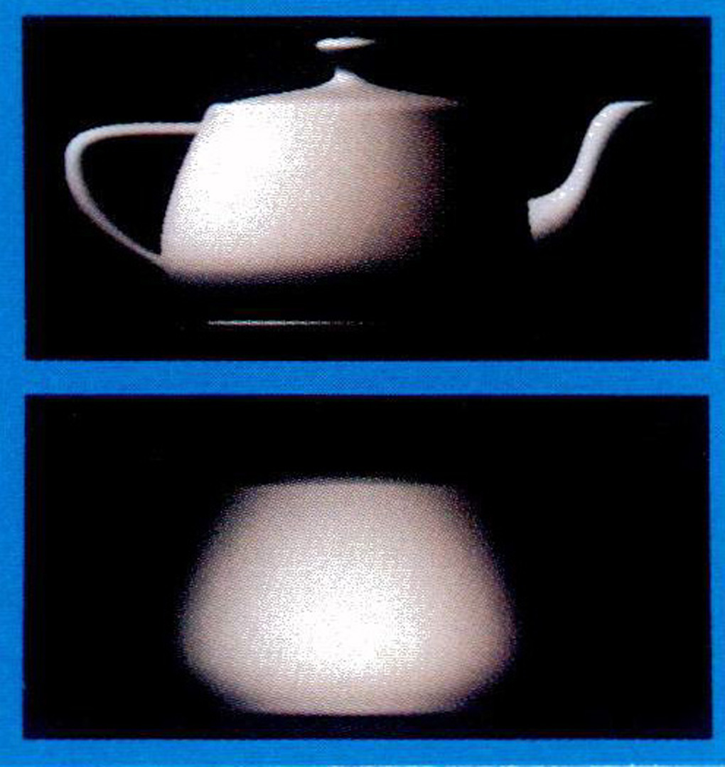
The G-buffer method is applied to NC machining. A total NC system is created that consists of all essential functions, such as tool path generation, path verification, and feed rate control. Moreover, any combination of object surface and tool shape is acceptable. By utilizing G-buffers created from a parallel projection, the required NC functions are realized as image processing operations. This ensures that the NC software is independent from surface description. Conventional rendering software can be used to make the G-buffers. Any surface can be milled if it can be rendered by parallel projection. Tool shape changes can be easily handled by changing the image processing filters. 3D examples of geometric surfaces, mesh data, and volume data are milled with this method, and the results show that the method is very effective.
References:
1. Zhang, D., and Bowyer, A., “CSG Set-Theoretic Solid Modeling and NC Machining of Blend Surfaces”, Proc. Y2nd Annual A CM Conf. Computational Geometry, pp. 236-245, 1986.
2. Sakuta, T., Kawai, M., and Am&no, Y., “Development of an NC Machining System for Stamping Dies of Offset Surface Method~, Proc. Autofact ’87, pp. 2-13 – 2- 27 (1987).
3. Kishinami, T., Kondo, T., and Saito, K., “Inverse Offset Method for Cutter Path Generation~, Proc. 6th Int’l Conf. Production Engineering, pp. 807-812, 1987.
4. Wang, W. P., and Wang, K. K., “Real-Time Verification of Multiaxis NC Programs with Raster Graphics”, Proc. IEEE int’l Con}. Robotics and Automation, pp. 166-171, 1986.
5. Wang, W. P., and Wang, K. K., “Geometric Modeling for Swept Volume of Moving Solids~, IEEE Computer Graphics and Applications, Vol. 6, No. 12, pp. 8-17 (1986).
6. Hook, T. V., ~Real-Time Shaded NC Milling Display~, Computer Graphics, Vol. 20, No. 4, (Proc. SIC;. GRAPH “86), pp. 15-20 (1986).
7. Atherton, P., Earl, C., and Fred, C., “A Graphical Simulation System for Dynamic Five-Axis NC Verification”, Proc. Auto}act ’87, pp. 2-1 – 2-12 (1987).
8. Kawashima, Y., Itoh, K., Nonaka, S., and Ejiri, K., “A Flexible, Quantitative Method for NC Machining Verification Using a Space Division Based Solid Model~, New Advances in Computer Graphics (Proc. CG Inter. national ’89), pp. 421-437 (1989).
9. Chappel, I. T., “The Use of Vectors to Simulate Material Removal by Numerically Controlled Milling”, Computer Aided Design, Vol. 15, No. 3, pp. 156-158 (1983).
10. Drysdale, R. L., mad Jerard, R. B., “Discrete Simulation of NC Machining”, Proc. 3rd Annual ACM Cony. Computational Geometry, pp. 126-135, 1987.
11. Jeraxd, R. B., Drysdale, R. L., Hauck, K., Schaudt, B., and Magewick, J., “Methods for Detecting Errors in Numerical Controlled Machining of Sculptured Surfaces”, IEEE Computer Graphics and Applications, Vol. 9, No. 1, pp. 26-39 (1989).
12. Jer~rd, R. B., Hussaini, S. Z., Drysdale, R. L., and Schaudt, B., “Approximate Methods for Simulation and Verification of Numerical Controlled Machining Programs”, Visual Computer, Vol. 5, No. 6, pp. 329- 348 (1989).
13. Saito, T., and Tak~hashi, T., “Comprehensible Rendering of 3-D Shapes”, Computer Graphics, Vol. 24, No. 4, (Proc. SIGGRAPH ’90), pp. 197-206 (1990).